


 中文简体
中文简体 Français
 русский
 Español
 عربى
عربى Deutsch



Thermodynamic Efficiency, Closed-Loop Fuel Injection, and Structural Mast Mechanics in Industrial Gas Forklift Production
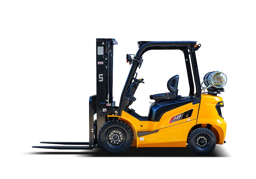
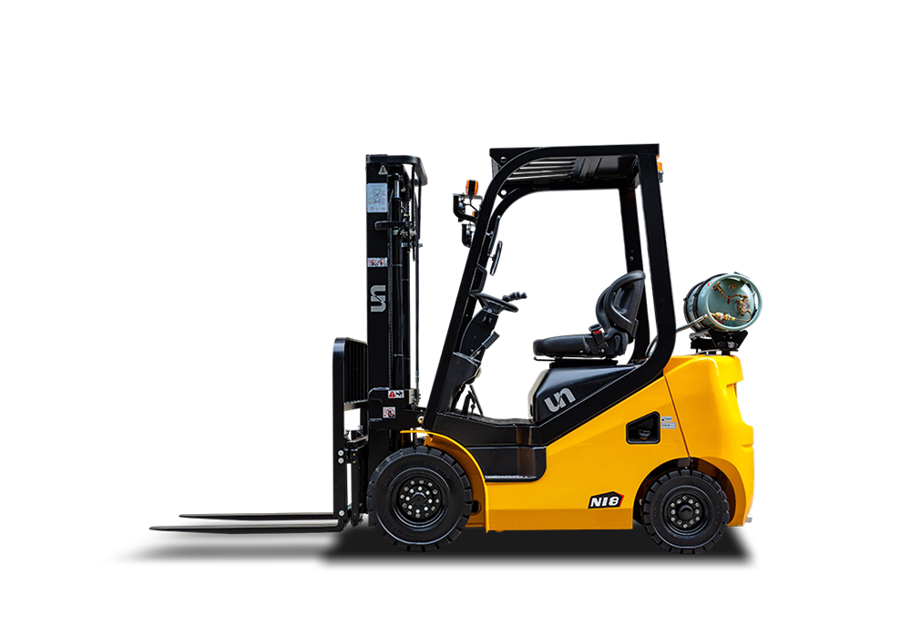
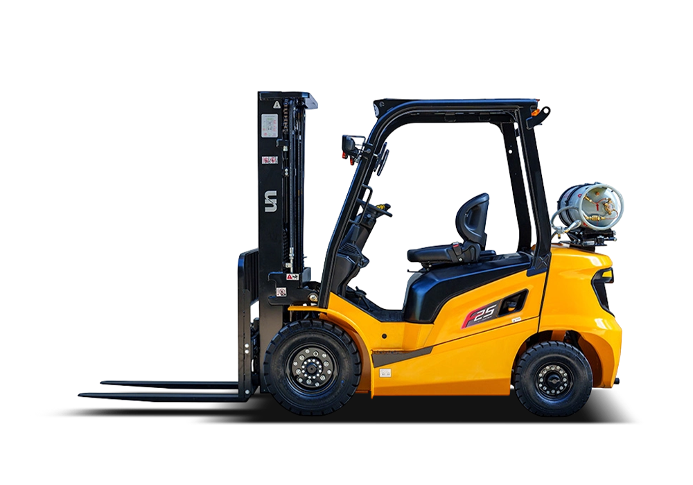
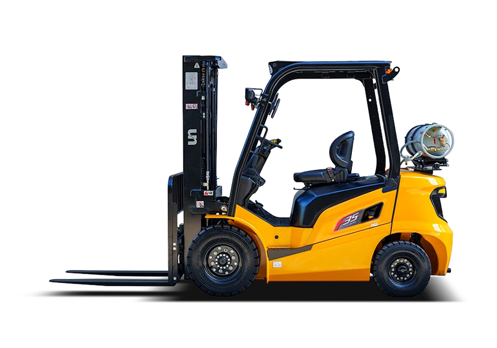
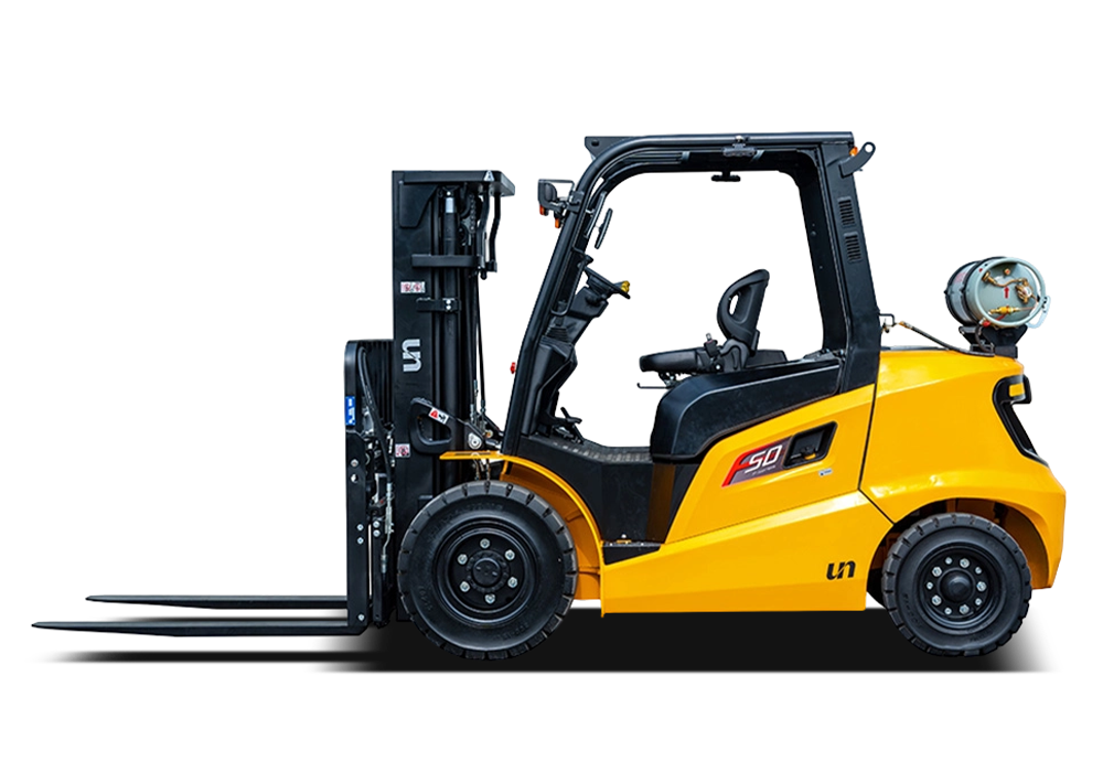
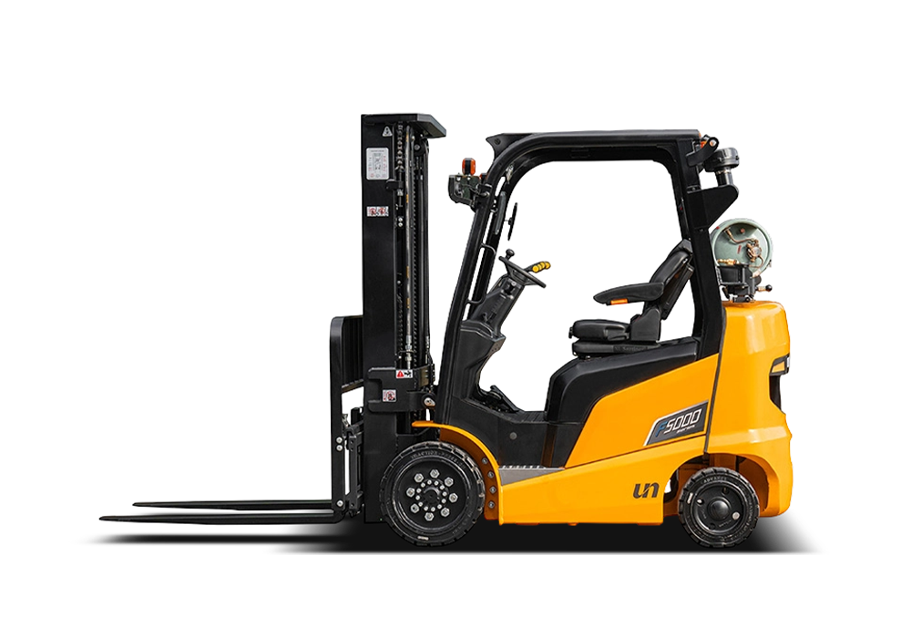
Admin 2026-05-28Optimizing high-throughput logistics hubs, outdoor lumber yards, and heavy industrial manufacturing floors requires material handling machinery capable of maintaining consistent torque curves, rapid refueling cycles, and sustained structural rigidity under maximum load vectors. A tier-one gas forklift manufacturer addresses these rigorous material handling demands by engineering heavy-duty chassis structures integrated with industrial internal combustion engines optimized explicitly for Liquefied Petroleum Gas (LPG). By replacing battery-charging downtime with ultra-fast fuel cell swapping and pairing the powertrain with high-displacement, variable-displacement hydraulic piston pumps, these manufacturing standards yield material handling units that maintain 100% mechanical output throughout multi-shift operations, bypassing the thermal and voltage degradation curves common in heavy electric material handling fleets.
Thermodynamic Efficiencies of Liquid Propane Gas Internal Combustion Engines
The operational advantage of an LPG-fueled forklift lies within the unique chemical composition and combustion physics of liquid propane compared to diesel or standard gasoline lines. Because propane enters the engine's intake manifold as a pre-expanded, highly volatile dry gas, it mixes uniformly with atmospheric oxygen at a molecular level, preventing the unvaporized fuel droplets that cause raw carbon soot deposits.
Industrial gas forklift power plants are built with heavy structural cast-iron engine blocks featuring specialized hardened valve seats to resist the dry, non-lubricating properties of vaporized gas fuel. Propane possesses a high octane rating of approximately 105 to 110 RON, allowing engine designers to utilize higher compression ratios—often reaching 10.5:1 or 11:1—without introducing hazardous pre-ignition knock or engine pinging. This high compression configuration boosts thermal efficiency, enabling a standard 2.5-liter industrial engine to produce a flat, reliable torque curve yielding 140 Nm to 160 Nm of torque at a low 1,600 RPM. This immediate low-end power is crucial for driving loaded forklifts up steep concrete warehouse ramps and across uneven outdoor tarmac surfaces.
Closed-Loop Electronic Fuel Vaporization and Stoichiometric Controls
To safely run internal combustion machinery inside large warehouse spaces, a gas forklift manufacturer must integrate sophisticated closed-loop fuel delivery mechanics to keep toxic emissions well below strict occupational health limits.
Liquid propane flows from the pressurized onboard cylinder at roughly 0.7 MPa to 1.2 MPa into a multi-stage engine vaporizer-regulator heated by the engine's cooling jacket water. This liquid-to-gas phase change drops the fuel pressure down to near-atmospheric levels. An Engine Control Unit (ECU) monitors data from a heated exhaust oxygen sensor (lambda sensor), continuously adjusting an electronic throttle body valve to maintain a perfect stoichiometric air-fuel ratio of 15.6:1 by weight. This precise adjustment ensures that a three-way catalytic converter can scrub out up to 98% of carbon monoxide (CO) and hydrocarbons (COH), ensuring the exhaust stream remains clean enough for indoor distribution operations.
Hydraulic Lift Circuits and Proactive Pressure Compensation Kinetics
Moving heavy steel coils, palletized components, or industrial machinery requires a fluid power system capable of handling extreme pressure spikes while giving the operator smooth, microscopic control over lifting and lowering speeds.
The hydraulic circuit engineered by a gas forklift manufacturer couples the main engine shaft directly to a high-pressure gear pump or a variable-displacement axial piston pump. When lifting a maximum rated load, the system raises the fluid pressure inside the steel hydraulic lines to an intense 18 MPa to 22 MPa. To stop the forks from jerky drops or sudden speed changes when the engine revs, the main valve assembly incorporates load-sensing, pressure-compensated flow control spool valves. These internal spools balance fluid flow using a series of springs and pilot channels, ensuring the mast lift cylinders extend at a stable, predictable velocity of 0.5 to 0.6 m/s regardless of whether the engine is idling or running at its maximum 2,500 RPM governor limit.
Engineering Fleet Configurations and Operational Load Ratings
Industrial logistics managers and safety directors must carefully balance a forklift’s rated load capacity, wheelbase dimensions, tire compound density, and engine output specifications against the physical architecture of their facilities. Selecting an incorrect chassis footprint or an inadequate counterweight ratio risks overloading structural floors or creating tip-over hazards during high-stacking procedures.
The table below details the engineering dimensions, engine performance metrics, hydraulic lift speeds, and load centers for standard industrial gas forklift manufacturing classifications:
| Forklift Chassis Classification | Nominal Rated Lift Capacity | Engine Displacement & Power Output | Standard Load Center Distance | Maximum Triplex Mast Lift Height |
|---|---|---|---|---|
| Compact Warehouse Core Line | 2,000 kg (4,400 lbs) | 2.0-Liter LPG / 38 kW Output | 500 mm Standard | 4,800 mm (15.7 ft) Fully Extended |
| Heavy-Duty Industrial Yard Unit | 3,500 kg (7,700 lbs) | 2.5-Liter LPG / 46 kW Output | 500 mm Standard | 5,500 mm (18.0 ft) Fully Extended |
| High-Capacity Infrastructure Frame | 5,000 kg (11,000 lbs) | 3.8-Liter LPG / 64 kW Output | 600 mm Extended | 6,000 mm (19.6 ft) Fully Extended |
Structural Mast Deflection Mitigation and Interlocking Rail Kinetics
When a forklift operator elevates a multiple-ton load several meters into the air, the lifting assembly is subjected to severe forward bending moments, side-to-side twisting forces, and sudden off-center shock loads caused by warehouse floor ruts.
To ensure zero structural failure under these stresses, a specialized gas forklift manufacturer molds the interlocking rails of duplex and triplex masts out of heavy-duty, hot-rolled steel channels. These rails feature a thick, wide flange profile designed to minimize structural twisting. The inner mast sections slide smoothly inside outer channels on oversized, sealed angled roller bearings that are pre-greased for life. Rather than placing the lifting chains directly in front of the operator's view, modern masts use a clear-view wide-visibility layout. This placement splits the heavy lift chains and dual primary lift cylinders to the far outer edges of the frame. This layout significantly improves the driver's forward visibility while spreading the lifting stresses evenly across both sides of the carriage, dropping structural rail deflection down to less than 1.5% at maximum extension heights.
Hydrostatic Transmissions and Multi-Disc Wet Braking Control Loops
Unlike cars that travel long distances at steady speeds, a warehouse forklift operates in a constant loop of short, rapid movements: driving forward five meters, stopping, raising a load, reversing five meters, and turning tightly inside narrow storage aisles.
To handle this non-stop directional switching without destroying standard friction clutches, high-tier gas forklifts utilize an advanced hydrostatic or specialized powershift transmission loop. A hydrostatic drive uses an engine-driven variable-displacement axial piston pump connected directly to high-torque hydraulic motors mounted right inside the drive axle hubs. When the operator presses the forward or reverse foot pedals, the pump adjusts its internal swashplate angle to change fluid flow instantly, allowing the machine to alter directions smoothly without requiring mechanical gear shifting. To ensure stopping power matching this fluid drive, the drive axle assemblies house an internal multi-disc wet braking system sealed completely inside a cooling oil bath. This oil immersion isolates the brake pads from outside warehouse dust, grime, and moisture, extending the service intervals of the brakes past 10,000 hours of operations.
Step-by-Step Production Assembly and Factory Quality Commissioning Protocol
Fabricating an industrial gas forklift requires strict adherence to robotic welding tolerances, automated hydraulic flushing routines, and rigorous safety testing. Following a structured factory manufacturing flow prevents line defects and guarantees that every completed machine leaves the production bay fully certified to lift its rated load capacities safely.
- Robotic Monocoque Chassis Welding and Structural Audit: Clamp heavy-gauge steel plates into a multi-axis robotic welding jig. Fuse the side frames, heavy hydraulic oil reservoir, fuel cylinder cradle, and main counterweight mounts into a unified monocoque chassis, inspecting all primary weld beads using high-resolution ultrasonic non-destructive testing (NDT).
- Drop-In Core Powertrain and Line Alignment: Lower the pre-assembled 2.5-liter industrial LPG engine block and transmission unit into the chassis isolation mounts. Connect the main drive shaft to the front drive axle hub using a digital laser alignment alignment tool to ensure shaft runout stays below 0.05 mm.
- Install and High-Velocity Flush the Hydraulic Matrix: Route the steel-braided, high-pressure hydraulic lines from the main control valves to the lift and tilt cylinders. Fill the system with hydraulic fluid and run a dedicated off-line oil filtration machine for 30 minutes, flushing out microscopic assembly dust down to a clean ISO 4406 16/13/10 cleanliness tier.
- Mount the Clear-View Mast and Lift Chains: Lift the assembled triplex mast onto the front axle frame anchor hinges, securing it with high-tensile bolts. Thread the leaf-style lift chains over the top sheaves, connect the chains to the primary carriage bar, and adjust the chain tension nuts until the forks rest perfectly level with the floor surface.
- Execute Full Load Stability and Tilt Testing: Drive the completed forklift onto a tilting hydraulic test platform and lock the wheels down. Secure a certified 3,500 kg test block onto the forks, lift it to its maximum height, and tilt the platform to verify the unit meets all standard lateral and longitudinal stability margins before final paint coating.
Root Cause Defect Analysis and Enterprise Field Troubleshooting
When an industrial gas forklift experiences a sudden drop in lifting speed, suffers from a hard-starting condition in freezing weather, or throws a hydraulic error code, field mechanics can quickly pinpoint the underlying defect by analyzing system operating pressures and fuel delivery metrics.
A common operational failure found in heavy-duty fleets is an engine freeze-up, where the exterior casing of the propane vaporizer develops a thick coat of white ice and stalls out the engine. This thermal breakdown is typically caused by a blocked cooling loop or a stuck engine thermostat. If rust or scale builds up inside the engine's coolant passages, it blocks the flow of hot water to the vaporizer regulator. Without this engine heat, the rapid pressure drop of the expanding propane gas chills the regulator body below 0°C, freezing any ambient air moisture on the casing and turning the liquid propane into an unvaporized slush that floods the engine. Field mechanics can fix this issue by thoroughly flushing out the engine radiator, replacing a worn thermostat, and checking the coolant hoses for internal kinking to ensure a constant supply of warming water reaches the regulator.
Another frequent field issue is mast drift, where elevated forks slowly creep downward on their own when the machine is turned off, presenting a serious workplace safety hazard. This height loss points directly to leaking internal piston seals inside the primary lift cylinders or a scratched spool valve valve seat. If fine grit slips past the hydraulic filters, it can scratch the soft rubber piston seals inside the lift cylinders, allowing pressurized oil to bleed slowly backward around the piston head. Technicians can diagnose this fault by raising a standard load, clamping off the primary oil supply lines, and measuring the drop rate; if the mast continues to creep down with the lines blocked, the cylinder must be torn down and rebuilt with fresh polyurethane lip seals, restoring safe load-holding performance.
For exclusive deals and latest offers, sign up by entering your email address below.
Stay In Touch
ADDRESS : NO.1 ROAD ONE, XINDENG NEW DISTRICT, FUYANG, HANGZHOU, ZHEJIANG, CHINA 311404.
PHONE : +86-571-8688 8355 (AMERICA)
PHONE : +86-571-8886 9363 (EUROPE)
PHONE : +86-571-8688 8377 (ASIA, AFRICA, OCEANIA)
EMAIL : [email protected]
EMAIL : [email protected](PARTS INQUIRY)

